The Baby Lidar ☺
It's finally time to play with our first piece of hardware!
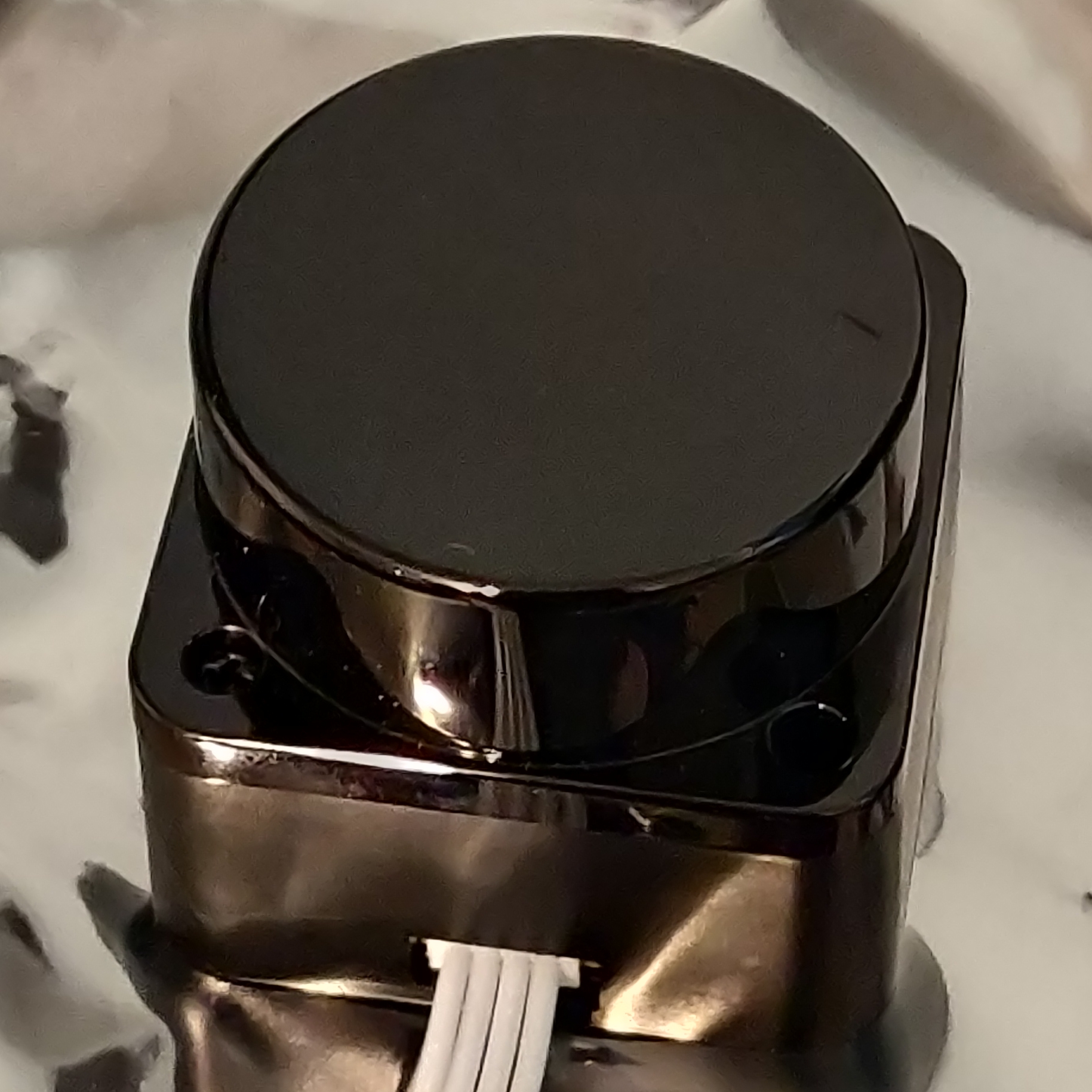
I would like to introduce the LD06, AKA Baby LiDAR!
LiDARs
So why do we even have a LiDAR? Well, LiDARs provide a means to get a slice of the world around you as distance data. This is extremely useful for mobile robots, since there really isn't another sensor that can give the same field of view as a LiDAR.
Generally speaking, there are two kinds of LiDAR, 2d and 3d. 3d LiDARs get distance values with both a vertical and horizontal angle. 2d LiDARs, like the LD06, only get distance values from a flat plane. This makes them far less versatile in the real world, but significantly easier to work with and cheaper.
To get a mental model of how a LiDAR works, think of a laser rangefinder, such as those used in golf. You point it at something, and it gives a distance reading at some frequency. Now think about what happens if we put that rangefinder on a spinning motor. as the motor spins the rangefinder, the rangefinder will read a different location each time, with a density of points proportional to is frequency. Given a high enough frequency, this readout will give you a 2d slice of the world around you as polar coordinates.
For a visualization, take a look at this diagram from the LD06 user manual:
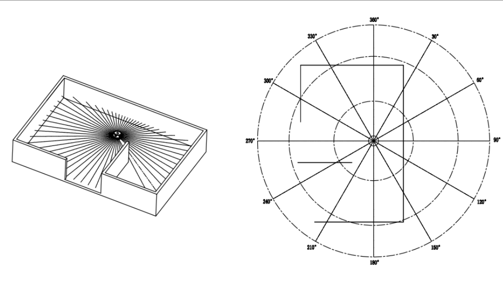
Like all sensors, LiDAR has operating limits. For LiDARs, these limits are generally its frequency and range. Unsurprisingly, the LD06 is pretty bad at both, reading at 10Hz with a max range of 8-10m. This means that care needs to be taken to avoid outpacing the speed of the LiDAR itself.
UART
The LD06 of course needs to connect to our board somehow. While industrial LiDARs generally use Ethernet for this purpose, our little baby lidar uses UART. UART, or RS232 (kinda, I'm not opening that debate) is a very simple protocol for communication between embedded processors. While I won't get super into the weeds with how UART is implemented, think of it as a very minimal layer over the idea of sending data over a wire as binary via high and low signals. In hardware, UART is implemented (In most modern uses) as simply two or even just one wire, like so:

UART is an asynchronous protocol, that is, it does not have a clock line. This means that without prior configuration, the receiver would have no way of knowing how fast the sender plans to send high and low bits. For UART, we call this rate baud, measured in bits per second (effectively). This gives the advantage of removing the clock wire and thus requiring less hardware, at the expense of anguish if you configure your reciver to a different baud than the sender.
Also worth noting is that UART has no link-layer error detection, so higher layer protocols using UART almost always include error detection methods such as Cyclical Redundancy Checks (CRCs) to ensure data integrity should there be electrical noise in the system.
Connecting Baby Lidar
Preamble aside, lets get the Baby connected. From the manual, the LD06 has the following pinout:

As you can see, the LiDAR actually only has a UART transmitter, which means we will only need a UART receiver (Rx) on the board side. The PWM input is unused, and the other two pins are simply power and ground.
While there are a variety of ways to connect these to the board, TinyKart is configured to use the following pins:
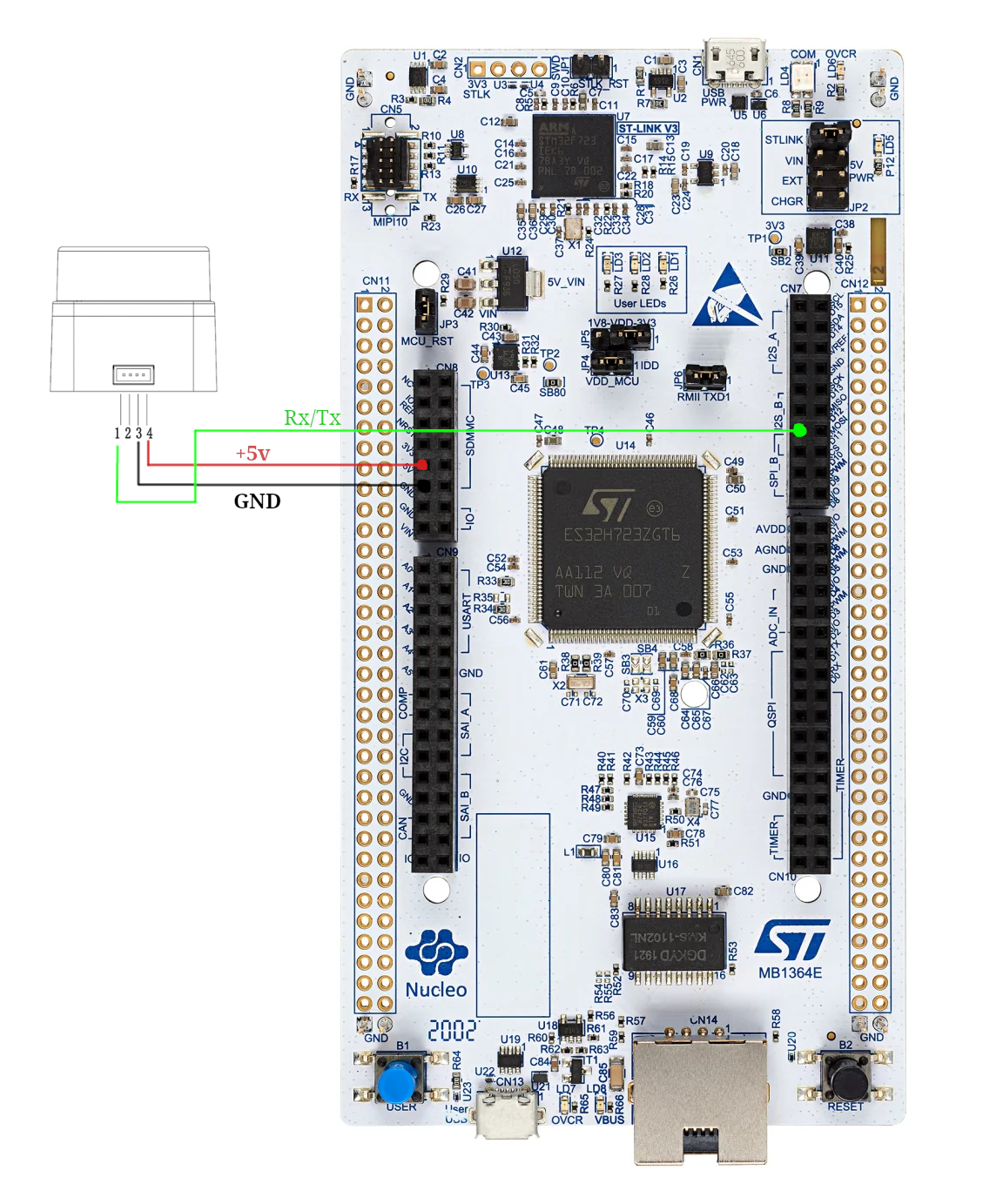
Go ahead and connect these to the respective pins on the wire connected to baby lidar. The end result should look something like this:
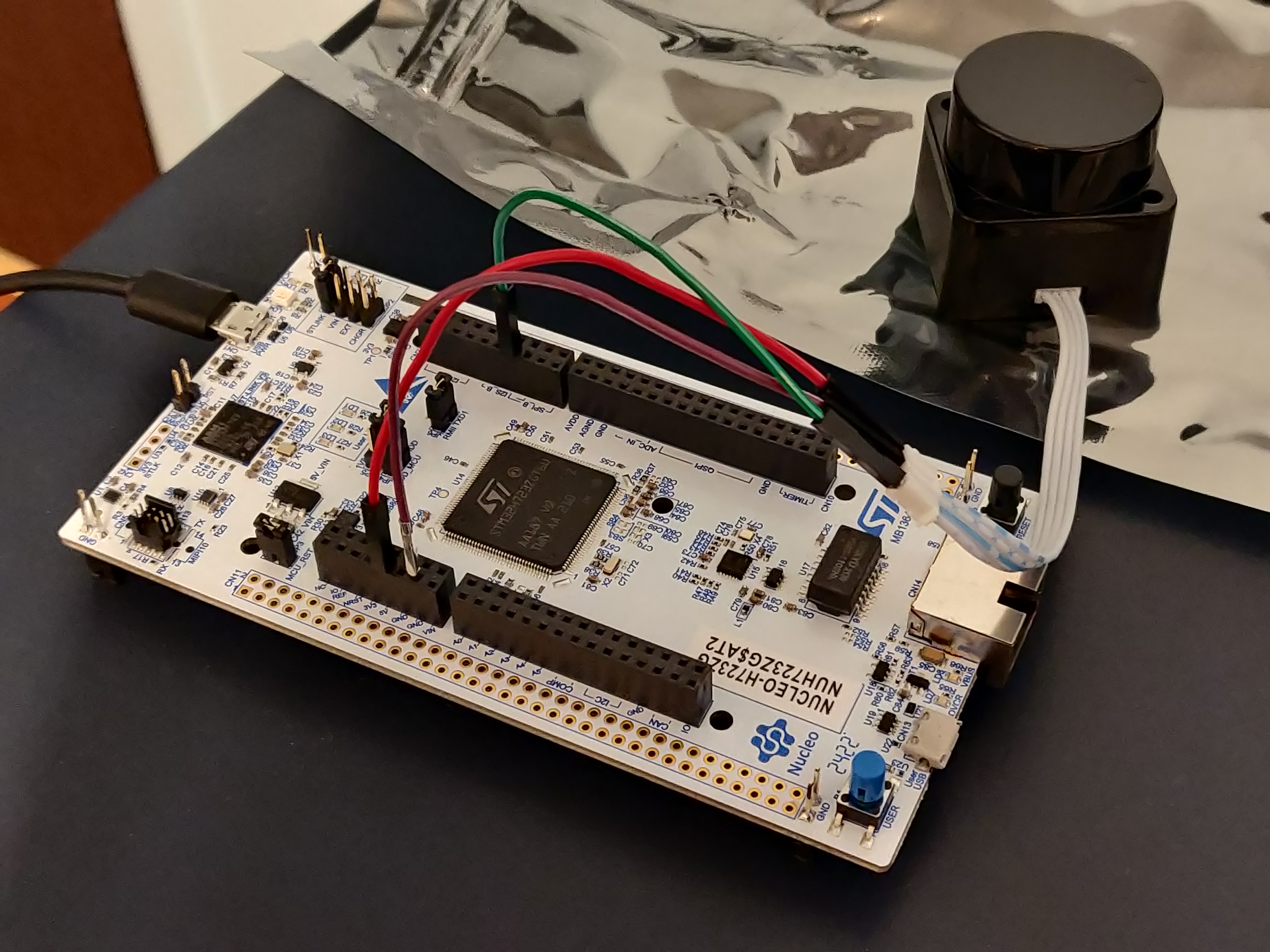
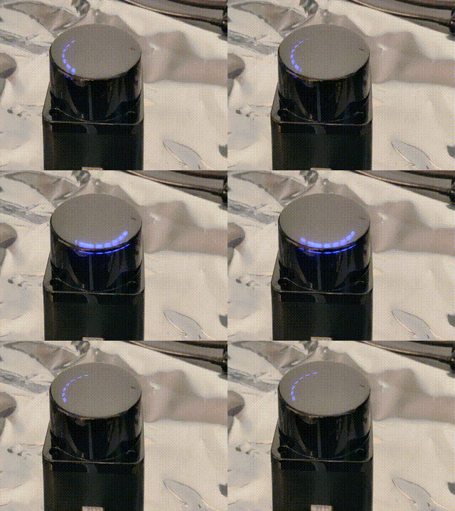
With that being said, it's time to see the little guy come to life! Just plug in the board, and the LiDAR should spin to life!
Reading Baby Lidar
First off, we need to figure out how to actually read the UART line connected to the LiDAR. This can be done in one of two ways:
- Polling: Checking if a byte has been received in the arduino loop()
- Interrupts: Having hardware call an interrupt request handler (IRQ) function whenever a byte arrives
Generally, polling is going to be slower but more convient, whereas interrupts require hardware support but allow for hardware to communicate in parallel with your programs' execution.
By default, Arduino essentially only allows for polling, as it uses the IRQ itself behind the scenes. This unfortunately is actually too slow for how fast the LiDAR runs, so we have to make our own approach using interrupts. This is actually quite complex and delves into STM HAL code, so the code won't be discussed here (if you're curious, check the dma.cpp file).
The LD06 sends its data in frames with the following format:
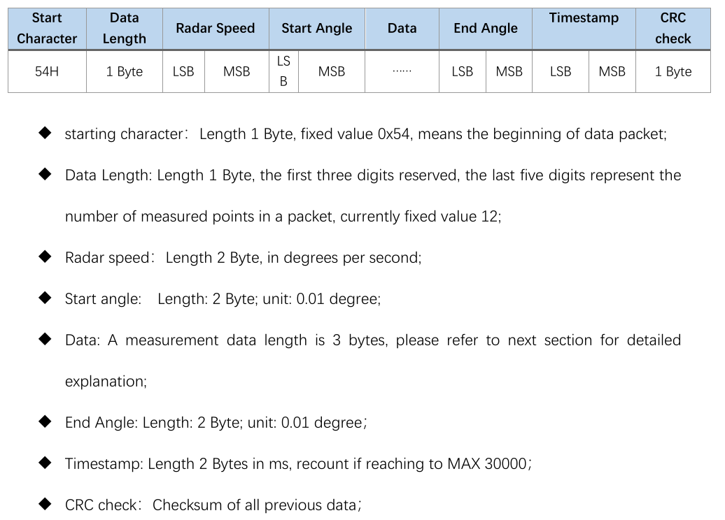
As you can see, each frame from the lidar will be 47 bytes, and contain data between some start and end angle. Notice
how
all data is in large integer values. This is because sending floats over the wire is quite inefficient, so we simply
scale
up the values and use ints instead. The LSB and MSB refers to least and most significant bit respectively. This
indicates
the endiness of the data, or the ordering of each byte in multibyte structures. For example, if 0x270F(9999 decimal)
is
sent over this UART protocol, then it will actually be read and sent as 0x0F27. While this seems insane, this is
actually
how the ARM processor on the board already stores the ints. So by doing this, we can do simple C pointer magic to read
the two bytes as a 16-bit integer:
packet.radar_speed = *reinterpret_cast<uint16_t *>(current_scan + 2);
With all this layed out, our approach looks like the following:
- LiDAR sends bytes over the UART
- UART peripheral triggers IRQ
- We copy a single byte to a buffer of bytes in RAM (literally just a uint8_t array)
- Repeat until we have 47 bytes
- Once we have 47 bytes, we need to figure out where the frame starts. To do this, we find the 0x54 start header. Align the buffer to now start at this byte.
- If that were to make us under 47 bytes, exit and wait for more
- Else, process the frame data into a C++ struct using the above pointer technique
This approach is implemented in the ld06 driver provided for your use.
Review
Alright, that was quite the infodump. Let's take a look at the code you'll be working with, and actually see what this looks like in action.
Open main.cpp.
On line 15 you'll see the creation of our driver:
LD06 ld06{};
Farther down in the setup, you'll see us configuring our callback to copy the buffer to the driver in the IRQ:
    // Init DMA and UART for LiDAR
    dmaSerialRx5.begin(230'400, [&](volatile LD06Buffer buffer) {
        // On each packet received, copy over to driver.
        ld06.add_buffer(buffer, 47);
    });
Finally, we poll the driver to see if a scan has been processed in the loop:
    noInterrupts();
    auto res = ld06.get_scan();
    interrupts();
Interrupts are disabled around the LiDAR to avoid issues when a new buffer arrives and starts copying right as we read the previous buffer (known as a race condition).
The processed scan frames have the following layout:
struct LD06Frame {
    /// The rotational speed of the unit, in degrees per second.
    uint16_t radar_speed;
    /// The starting angle of this scan, in degrees.
    float start_angle;
    /// Distance readings.
    Range data[12];
    /// The ending angle of this scan, in degrees.
    float end_angle;
    /// The timestamp of this scan, in ms. This will roll over at 30000.
    uint16_t timestamp;
    /// The CRC check from the lidar.
    uint8_t crc8;
Remember that each range is just a distance reading, which occurred at some angle. To retrieve this data, we must interpolate the index with the start and end angles:
    [[nodiscard]] float get_angle_of_reading(uint8_t reading_idx) const {
        assert(reading_idx < 12);
        auto angle = start_angle + get_step() * float(reading_idx);

        if (angle > 360.0) {
            angle -= 360.0;
        }
        return angle;
    }
With this, we have all that we need to interpret frames from the LiDAR! Armed with this information, I recommend messing around with main.cpp to log data read by the board, and monitor the results by using the PIO monitor.
To open the monitor, first find the terminal icon in the bottom gutter near the upload button. This will open a terminal
with the pio command sourced. Next, open a monitor to view the boards printfs by
running pio device monitor -b 115200.
Scan Building
Cool, so we can read frames. As it turns out, this actually isn't all that useful. This is because each frame actually only covers a very small region of the overall scan. This makes sending the LiDAR data much easier, but makes processing on our end a bit more complicated. To remedy this, we must assemble scans by hand, as we receive frames. During this process, we can also do other forms of filtering on the frames to make the data easier to work with. This is generally called scan preprocessing, and is done on actual industrial robots.
Our approach:
- for each frame:
- If frame is in the range we want to read
- If reading is noisy, ignore it
- Convert each range to (x, y) coordinates about the lidar, from polar. Store this in a buffer.
- else, if the last frame was in range, and thus our desired scan area is full, return the completed scan.
- If frame is in the range we want to read
This is implemented in the ScanBuilder class:
    /// Adds a frame to the scan builder
    std::optional<std::vector<ScanPoint>> add_frame(const LD06Frame &frame) {
        // Filter to in range
        if (scan_in_range(frame.start_angle, frame.end_angle)) {
            last_scan_in_bounds = true;

            // Convert points to cartiesian points
            for (int i = 0; i < 12; ++i) {
                // Skip points that are outside the scan, but some in the frame are
                if (!scan_in_range(frame.get_angle_of_reading(i), frame.get_angle_of_reading(i))) continue;

                auto [range, angle] = frame.get_range_in_polar(i);
                float radian_angle = angle * (float(M_PI) / 180);

                float x = range * sinf(radian_angle);
                float y = -(range * cosf(radian_angle));

                // Read noisy points as 0, which is what unreadable points are also received as
                if (frame.data[i].confidence < 150) {
                    x = 0;
                    y = 0;
                }

                // Convert from mm to m
                x /= 1000;
                y /= 1000;

                // Apply lidar offset
                if (x != 0 && y != 0) {
                    x += lidar_offset.x;
                    y += lidar_offset.y;
                }

                buffer.push_back(ScanPoint{x, y});
            }
        }
            // Full scan area covered
        else if (last_scan_in_bounds) {
            last_scan_in_bounds = false;

            return std::move(buffer);
        }
In the tinykart default implementation, this is configured to read from -90 to 90 degrees:
ScanBuilder scan_builder{180, 360, ScanPoint{0.1524, 0}};
Putting it all together
Time for you to get your hands dirty! Before anything else, replace your loop with the one below:
void loop() {
    noInterrupts();
    auto res = ld06.get_scan();
    interrupts();

    // Check if we have a scan frame
    if (res) {
        auto scan_res = *res;

        // Check if frame erred
        if (scan_res) {
            auto maybe_scan = scan_builder.add_frame(scan_res.scan);

            // Check if we have a 180 degree scan built
            if (maybe_scan) {
                auto scan = *maybe_scan;

                logger.printf("*****START SCAN******\n");
                for (auto &pt: scan) {
                    logger.printf("Point: (%hu,%hu)\n", (uint16_t) (pt.x * 1000), (uint16_t) (pt.y * 1000));
                }
                logger.printf("*****END SCAN******\n\n");
            }
        } else {
            switch (scan_res.error) {
                case ScanResult::Error::CRCFail:
                    logger.printf("CRC error!\n");
                    break;

                case ScanResult::Error::HeaderByteWrong:
                    logger.printf("Header byte wrong!\n");
                    break;
            }
        }
    }
}
This code builds on the review section, and now also prints out completed scans, once they are built. Flash this to your board, and open the PIO monitor. You should see data blaze by.
Try putting our hand around the LiDAR. You should see the values lower. Something to note about these cartisian coordinates is that they are in right-hand-rule. That is, x is positive forwards and y is positive to the left. This is the standard coordinate system in robotics.
Homework
Now it's time for your challenge. Given the above code, create a program that prints "GOTCHA!" whenever someone is 50cm or less from the back of the LiDAR. This will only require modifying things in main.cpp, and only in loop and the globals. If you have any questions on units, formats etc., read the docs in the code! This is good practice for working on larger projects, since rarely will there be guides as verbose as this one to step through the code.
Good luck!